Azhar Shahzad
Administrators
-
Joined
-
Last visited
-
Advantages of steel construction1. ReliabilitySteel structures are very reliable. The reasons for this reliability include consistency and uniformity in properties, better quality control because of factory manufacture, large elasticity, and ductility. If different specimens of some types of steel are tested in the laboratory for yield stress, ultimate strengths and elongations, the variation is much lesser than other materials like concrete and wood. Further, because of truly homogeneous and elastic material, steel satisfies most of the assumptions involved in the derivation of the analysis and design formulas and the results obtained and reliable. This may not be the case in concrete structures because of heterogeneous material, cracking and non-linearity of stress-strain relationship. 2. Industrial behaviorRolled steel sections are manufactured in factories. Also, the members may be cut and prepared for assembly in factories wile only joining of these components is carried out at the site by installing rivets or bolts and by welding different components. Sometimes parts of the structure are also assembled in the factories, that is, there is a great adaptation to prefabrication. Manual errors reduce greatly in such cases, the speed of construction increases, and the total cost reduces. 3. Lesser construction time / greater erection speedBecause of the industrial nature of steel construction. Progress of the work is fast making the structures economical. The reason is that these structures can be put to use earlier. The reduction in labor cost and overhead changes and the benefits obtained from the early use of the building contribute to the economy. 4. High strength and light weight natureThe high strength of steel per unit weight means that the dead loads will be smaller. It is to be noted that dead loads are a bigger part of the total loads on structure. When dead load reduces, the underneath members become still smaller due to less weight acting on them. This fact is of great importance for long-span bridges, tall building, and for structures having poor foundation conditions. 5. Uniformity, durability and performanceSteel is a very homogeneous and uniform material. Hence, it satisfies the basic assumptions of most of the analysis and design formulas. If properly maintained by painting, etc. the properties of steel do not change appreciably with time, whereas the properties of concrete in a reinforced concrete structure are considerably modified with time. Hence, steel structures are more durable. 6. ElasticitySteel behaves closer to design assumption than most of the other material because it follows Hooke’s law up to fairly high stresses. The stress produced remains proportional to the strain applied oft the stress-strain diagram remains a straight line. The steel sections do not crack or tear before ultimate load and hence the moments of inertia of a steel structure can be definitely calculated. The moments of inertia obtained for a reinforced concrete structure are rather indefinite. 7. Ductility and warning before failureThe Property of a material by which it can withstand extensive deformation without failure under high tensile stresses is said to be it ductility. Mild steel is a very ductile material. The percentage elongation of a standard tension test specimen after fracture can be as high as 25 to 30%. This gives visible deflections of evidence of impending failure in case of overloads. The extra loads may be removed from the structure to prevent collapse. Even if collapse does occur, time is available for occupants to vacate the building. In structural members under normal loads, high stress concentrations develop at various points. The ductile nature of the usual structural steel enables them to yield locally at those points, thus redistributing the stresses and preventing premature failures. 8. Additions to existing structuresAdditions to existing steel structures are very easy to be made. Connections between new and existing structures can be employed very effectively. New bays or even entire new wings can be added to existing steel frame building, and steel brides may often be widened. 9. Possible ReuseSteel sections cab be reused after a structure is disassembled. 10. Scrap valueSteel has a scrap value even though it is not reusable in its existing form. 11. Water-tight and air-tight constructionsSteel structures provide completely impervious construction and structures like reservoirs, oil pipes, gas pipes, etc. are preferably made from structural steel. 12. Long span constructionHigh-rise buildings, long span bridges and tall transmission towers are made up of structural steel. Industrial buildings up to a span of 90.m can be designed by plate girders or trusses. Bridge spans up to 260.m are made with plate girders. For through truss bridges, Bridge spans of 300.m have been used. 13. Temporary constructionFor temporary structures, steel construction is always preferred. Army constructions during war are mostly made out of structural steel. The structures may be disassembled by opening few bolts, component parts are carried to new places are the structure is easily reassembled. Disadvantages of steel construction1. High maintenance costs and more corrosionMost steels are susceptible to corrosion when freely exposed to air and water and must therefore be periodically painted. This requires extra cost and special care. The use of weathering steels, in stable design applications, tends to eliminate this cost. If not properly maintained, steel members can lose 1 to 1.5 mm of their thickness each year. Accordingly, such constructions can lose weight up to 35% during their specified life and can fail under the external loads. 2. Fireproofing costsAlthough steel members are incombustible, their strength is tremendously reduced at temperatures prevailing in fires. At about 400ºC, creep becomes much more pronounced. Creep is defined as plastic deformation under a constant load for a long period of time. This produces excessively large deflections/deformations of main members forcing the other members to higher stresses or even to collapse. Steel is an excellent conductor of heat and may transmit enough heat from a burning compartment of a building to start fire in other parts of the building to start fire in other parts of the building. Extra cost is required to properly fireproof the building. 3. Susceptibility to bucklingThe steel sections usually consist of a combination of thin plates. Further, the overall steel member dimensions are also smaller than reinforced concrete members. If these slender members are subjected to compression, there are greater chances of buckling. Buckling is a type of collapse of the members due to sudden large bending caused by a critical compressive load. Steel when used for columns is sometimes not very economical because considerable material has to be used merely to stiffen the columns against buckling. 4. Higher initial cost / less availabilityIn few countries, steel is not available in abundance and its initial cost is very high compared with the other structural materials. This is the most significant factor that has resulted in the decline of steel structures in these countries. 5. AestheticsFor certain types of buildings, the steel form is architecturally preferred. However, for majority of residential and office buildings, steel structures without the use of false ceiling and cladding are considered to have poor aesthetic appearance. A considerable cost is to be spent on such structures to improve their appearance. Cladding is a covering of metal, plastic or timber put on the surface of a structural member to completely encase it. The cladding not only protects the member but also improves its appearance.
-
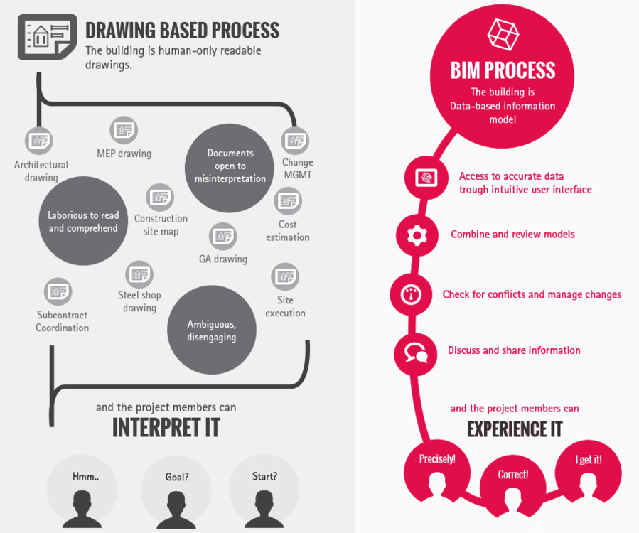
Definition of BIM: Building information modelling (BIM) is a digital representation of physical and functional characteristics of a facility. A BIM is a shared knowledge resource for information about a facility forming a reliable basis for decisions during its life-cycle; defined as existing from earliest conception to demolition. BIM benefits: Faster drafting without loss of cost and quality High level of customization and flexibility Optimization of schedule and cost Seamless coordination and collaboration Conflict detection and risk mitigation Easy maintenance of building life cycle Here is the nice info-graphic which compares BIM based process to the 2D drawings based process: Learn more about BIM solutions for structural engineers

-
1. BIM will be the backbone of future Construction Building Information Modeling is taking over the industry globally at the speed of light. In the UK, for example, the industry adoption rate has boomed from 13% in 2010 to 39% in only two years and many countries are introducing initiatives such as national BIM recommendations to push the adoption forward. It is reasonable to expect this trend to continue as the construction industry recovers from recession and as BIM continues its path towards becoming an industry requirement. Whether you are studying structural engineering, construction engineering or architecture, expect BIM to be a major factor and competitive advantage upon graduation. 2. The "I" in the BIM will become even more Significant While impressive illustrations and 3D models are a highly visible part of BIM, robust opportunities for collaboration, coordination, fabrication, as well as, integration to production automation systems and machinery is what really puts the “I” in BIM. Information management and Integration between models allows each professional to focus on what they do best while simultaneously improving clash checking and accuracy. BIM makes relevant information available to everyone when they need it. Models become more than a sum of their parts, making BIM a highly attractive tool for both companies and professionals in related industries. 3. The Industry will look for BIM experts instead of CAD Assistants With the industry changing at a rapid pace, companies start looking for skilful BIM users to keep up with this speed of change. To mention a few sought-after skills, employers start looking for experts who can create and develop different models and perform analyses and simulations based on these models. Companies who are at early adoption stages of BIM are looking for BIM specialists who are capable of implementing BIM, managing and modeling all project information and also educating others within the organization. Academia and schools need to meet this demand by delivering a new generation of professionals who are fluent in BIM. 4. With BIM You will... Practically everyone involved in the design and construction process will gain benefits from BIM. Engineers, architects and contractors can virtually walk through construction models, explore structural components and details, and identify any potential design, construction or operational issues. BIM allows builders to bring even to the most complicated structures into reality by enabling the high detail modeling of multiple materials while simultaneously saving time, resources and space. Users will be able to focus on the essential instead of the menial. Learn more about BIM solutions for structural engineers

-
Study some basic mathematical topics like Geometry, Vectors, and Matrices etc. It will greatly increase your understanding towards engineering mechanics. Must read relevant theory first before attempting problems. Start from easy problems then go on as your concepts developed.
-
By building up environment Civil Engineers play with nature... Civil engineering is a professional engineering discipline that deals with the design, construction, and maintenance of the physical and naturally built environment, including works like roads, bridges, canals, dams, and buildings. Why Become a Civil Engineer? 1. Civil engineers create the world around us Civil engineers are the unsung heroes of the engineering world. Yet this jack-of-all-trades discipline is an incremental part of creating everything from tall skyscrapers and complex stadiums to bridges, railways and tunnels. As a civil engineer, your work influences where people work, relax, learn and live. You will be a part of helping society to become more advanced by adapting the infrastructure to meet challenges brought on by new technologies, population growth and climate change. Civil engineers know that even the simplest structure can include hundreds of “unknowns” which they have to be able to identify and solve in order to ensure the structure is operational, stays safe and stands the trial of use, environment and age. In addition to all this, civil engineers also play a key role during emergencies like droughts or natural disasters by helping those affected to recreate their living environment and the infrastructure that provides for their basic needs. 2. Civil engineers never have a dull moment Civil engineers can work in a versatile range of positions and projects. Civil engineering specializations such as structural, environmental, geo-technical and transportation engineering all entitle challenging, constantly changing work environments and require creativity, adaptability, good problem-solving skills and ability to think on one’s feet. As a civil engineer, despite your area of specialization, you need to be sensitive to local and environmental challenges as well as to the requirements of different construction project participants. You need to have attention to detail while simultaneously understanding “the bigger picture”. In addition to the wide spectrum of challenges, the versatility of projects civil engineers can participate in ensures that you are unlikely to have a dull moment at work. You can work below the surface delivering tunnels, underground railways and energy and water supplies as well as above the surface creating roads, bridges, stadiums, hospitals, skyscrapers and many more. As a civil engineer, you are likely to be constantly on the move, sharing your time between the site, the office and perhaps even different geographical locations. 3. Civil engineers have a monument to show that they were there While civil engineering can be somewhat stressful, the profession includes a huge sense of accomplishment to make it all worthwhile. Throughout history, civil engineers have participated in some of the most ambitious and incremental projects known to mankind. World-known ventures such as the Hoover Dam, the Great Wall of China and the Hardanger Bridge are tokens of the hard work and expertise of civil engineers. While you might have to start your civil engineering career with slightly smaller projects, the fact remains that by the end of the day you will have a monument to prove that "you've been there". You know all the challenges and effort that went into transforming the blueprints into a fully functional structure. What do you think about Civil Engineering?

-
Procedure Suppose A and B are two distance points whose difference of level is to be determined as in the following figure, Place the staff over point A and set up the instrument at suitable distance towards B. The suitable distance between instrument and staff can be about 25 meters. Take a sight on the staff, that reading is called Back Sight (B.S). Now, move the staff to a new position towards B and take the reading, this will be a Fore Sight (F.S). Care should be taken to make the F.S equal to preceding B.Sm, by doing this we will eliminate the effect of curvature and refraction. Now, move the instrument to a new position and take the reading on the previous position of the staff. This position of staff is known as Change Point (C.P) and this reading will be Back Sight (B.S). Now, shift the staff to the point B and take reading, this reading will be Fore Sight. Setting up of instrument means careful leveling of instrument so, correct reading can be taken. It is not necessary to move in the straight line from A to B. If due to any reason F.S is not equal B.S then this error due to curvature and refraction can still be eliminated by making, ∑ (Back Sight distances) = ∑ (Fore Sight distances)

-
Definition of Water Consumption (W.C) It is the amount of water consumed by a community in one day. It is usual to express water consumption in litres/capita/day. Average water consumption is usually 150 to 600 lpcd. Classification of W.C according to Use No. Purpose Use Quantity 1 Domestic Sanitary, Drinking, Washing, Bathing, Cooking, Gardening etc. ~ 50-250 lpcd 2 Commercial and Industrial Markets, Office buildings, Dental clinics, Private Schools, Garages, Workshops etc. ~ 12.2 cube m/1000 sq. m of floor area/day 3 Public Use Public buildings i.e. Tower halls, Jails, Schools, Street washing, public toilets, gardens + Fire fighting ~ 10-20% of total water supply 4 Unaccounted Loss of water through leaks, Unauthorized connections ~ 10-15% of total water supply Terms related to Water Consumption There are some important terms related to water consumption which are listed below, Average Daily Consumption Maximum Daily Consumption Peak Hourly Consumption 1 - Average Daily Consumption It is the average amount of water consumed by a community in one day divided by the number of people served. 2 - Maximum Daily Consumption It is the maximum water consumption during any one day in the year. It is about 150 to 180% of average day consumption. 3 - Peak Hourly Consumption: The peak consumption during any hour of the year excluding fire demand is called Peak Hourly Consumption. It is around 150% of the maximum daily consumption. Ratios of water consumption used in Design Most common ratios that are being used in the design of water distribution system for a certain community are as follows, Maximum Day : Average Day = 1.5 : 1 Peak Hour : Maximum Day = 1.5 : 1 Peak Hour : Average Day = 2.25 : 1 The above ratios can be different depending upon the specific needs of the community and design criteria.


-
Object This System provides us with accurate horizontal and vertical measurements and gives us the position of observer in terms of Latitude and Longitude. Advantages This system is fast replacing with conventional methods of surveying like Triangulation, Traversing etc. It no longer requires the inter-visibility of station points. The conventional techniques are still required for detail surveying. The horizontal and vertical control can easily be established with the help of GPS. Instruments This system basically requires the receiver which is setup at the point of observation. The second part of the equipment is no of satellites which are 18, launched into 6 different orbits.Each orbit have three satellites with 120 degrees interval. The height of satellite is about 20,000 km with orbiting velocity of 11hr 58min. The GPS is controlled from an airforce base in California. Procedure The GPS position is achieved by the precise measurement of the distance between the satellite & the receiver at an instant of time. For a three dimensional measurements three or four satellites will be needed depending upon the quality of receiving equipment. It requires highly accurate clocks both in the transmitter and in the receiver to measure the precise distance between them. Applications This system gives us the accurate geographic position required for land surveying. It is used for navigation purposes in Aircraft,Ships,Submarines etc. It is now exceedingly used to locate the enemy targets and subsequently hitting them by GPS information guided missiles. For public use simpler version are available for locating the vehicles, the individuals and the parties, in hiking and mountaineering expeditions and other number of applications.
-
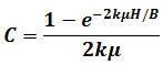
Sewer design requires prior knowledge of soil and site conditions to determine overburden loads that will be placed on buried pipes. Total Load = Backfill Load + Live Load Backfill Load (W): It depends upon following factors: Trench Width (B) Depth of Burial i.e, depth of fill above pipe (H) Unit Weight of Fill Material (w) Frictional Characteristics of Backfill Live Load : Live Loads on the Surface rarely influence design of sanitary sewer because of their Great Depth and Small Size. Backfill Load on Sewers Backfill load on buried pipes can be calculated using Marston's equation. W = CwB2 W = Load on the pipe per unit length, Kg/m w = Weight of the backfill material per unit volume, Kg/m3 B = Width of trench, m B = 1.5 D + 0.3 m (as minimum) D= Diameter of the sewer in m C = a coefficient depending upon depth of fill on top of the pipe and character of construction fill materials. μ = Coefficient of sliding friction k = Ratio of active lateral pressure to vertical pressure kμ = 0.1 to 0.16 for most soils (0.11 for saturated clay) H = Depth of fill above the top of the pipe, m B = Width of the trench, m For structural stability, strength of sewer as determined by 3-Edge Bearing test should be greater than backfill load on the Sewer.
-
Chemical weathering, or chemical decomposition, involves several important reactions between the elements in the atmosphere and those in the mineral of the earth's crust. In these processes, the internal structures of the original minerals are destroyed, and new minerals are formed, with new crystal structures that are stable under conditions at the earth's surface. Water is of prime importance in chemical weathering. It takes part directly in the chemical reaction. It acts as a medium to transport elements of the atmosphere to the minerals of the rocks where reactions can occur, and it removes the products of weathering to exposed fresh rock. The chemical reactions involved in the decomposition consist of the following three main groups i.e. Hydrolysis, Dissolution, and Oxidation. 1. Hydrolysis The chemical union of water and a mineral is known as hydrolysis. The process involves not merely absorption of water, as in sponge, but a specific chemical change in which a new mineral is produced. In hydrolysis, ions derived from one mineral reach with the H+ or OH- ions to produce a new mineral. A good example of hydrolysis is the chemical weathering of k-feldspar. Two substances are essential: carbon dioxide and water. The atmosphere and the soil contain carbon dioxide, which unites with rain water to form carbonic acid. If k-feldspar comes in contact with carbonic acid, the following chemical reaction occurs: 2KAlSi3O8+ H2CO3 + H2O → K2CO3 + Al2Si2O5(OH)4 + 4SiO2 Hydrolysis is an extremely important weathering process because it acts on the feldspars and ferromagnesium minerals, the dominant minerals in most rocks. 2. Dissolution Water is one of the most effective and universal solvent known. Because of the polarity of the water molecule, practically all minerals are soluble in water to some extent. The water molecule is polar and behaves like a tiny magnet. It acts to loosen the bonds of ions at the surface of minerals with which it comes in contract. Some rock types can be completely dissolved and leached away by water. Rock-salt is perhaps the best known example. It is extremely soluble, surviving at the earth's surface only in the most arid regions. Gypsum is less soluble than rock salt, but is also easily dissolved by surface water. Few out crops of these rocks occur in humid regions. Limestone is also soluble in water, especially if the water contains carbon dioxide. The chemical analysis of river water illustrates the effectiveness of dissolution in the weathering of rocks. Fresh rain water contain relatively little dissolved mineral matter, but running water soon dissolves the more soluble minerals in the rock and transport them in solution. Each year the rivers of the world carry about 3.9 million metric tons of dissolved minerals to the oceans, so it is not surprising that sea water contains 3.5% (by weight) dissolved salts, all of which were dissolved from the continents by pure rain water. 3. Oxidation Oxidation is the combination of atmospheric oxygen with a mineral to produce an oxide. The process is especially important in the weathering of minerals that have high iron content, such as olivine, pyroxene, and amphibole. The iron in silicate minerals unites with oxygen to form hematite or limonite. Hematite is deep red, and if it is dispersed in sandstone or shale, it imparts a red color to entire rock.
-
All rocks, when exposed for sufficient length of time to the atmosphere, undergo decay from disintegration and decomposition, together referred to as weathering. Disintegration is the break down into small particles by the action of mechanical agents of weathering such as rain, frost etc, decomposition is the breakdown of mineral particles into new compounds by the action of chemical agents such as acid in air and in rain and river water. Denudation is the general term used for the wearing down of land areas by the processes originating and acting at the earth’s surface. It includes both weathering and erosion. In addition to the atmospheric processes, agents of erosion (rivers, moving ice, water waves) contribute to the deduction of the land in their particular spheres of action, they also transport weathered and eroded material away from areas where it is derived, to from deposits of sediments elsewhere. Agents of Weathering 1. Rain The mechanical action of rain consist mainly in the washing of loose particles of soil and rock to lower levels. This phenomenon is known as rain-wash. It is the means by which rivers receive much of the sediments they carry in suspension. The chemical weathering effects of the rain are seen its solvent action on some rocks notably limestones. The process depends on the pressure of feeble acids, derived from gases such CO2 and SO2 which are present in air in small quantities and which enter into solution in rain water. The denuding effects of heavy showers and rain-storms may be very sever, especially in regions where a covering of vegetation is lacking. It cuts gullies in the surface of the ground, some of considerable size and may cause great damage by the destruction of roads and livestock. Heavy rains also promote land slides. Vegetation protects the ground from the immediate disintegrating effects of rainfall. 2. Frost In cold climates the action of the frost is to break off angular fragment from exposed rock surface, a process sometimes referred to as ice-wedge. Water enters rock along pores, cracks and fissures. On freezing it expands and occupies about 10% greater volume exerting a pressure of about 2000 lbs per square inch. This is therefore like a miniature blasting and brings about the disintegration of the rock. The loosened particles fall from the mass and accumulate as heaps of talus at lower levels and this material may later be consolidate into a deposit known as breccia. 3. Wind It is one of the two natural agents which transport rock material against gravity. Its effect is three-fold. First it removes loose particles of rock decay as it blows over a surface, then charged with these grains the wind act as an abrading sand-blast driving the grains against rock surfaces which becomes worn and polished in course of time. Thirdly the blown grains are accumulated to from sand-dunes. Lines of communication may be seriously affected by wind-blown sand in arid countries. It is on record that the telegraphic wire on the trans-Caspain railway was worm down to half of its diameter in eleven years, and renewal was then made. To avoid accumulation of sand alongside railway embankments in Sudan, culverts have been made to allow for easy passage of the wind and its load sediments. 4. Insolation When a rock surface is exposed to a considerable daily range of temperature, as in arid and semi-arid regions, the expansion which occurs during the day and contraction at night, constantly repeated have a weakening effect on the texture of the rock over a period of time . The outer heated layers tend to pull away from the cooler rock underneath a process known as exfoliation. By the unequal expansion and contraction of its mineral constituents the strain is set up in a rock and its texture is loosened. This kind of weathering is prevalent in climates where high day and low night temperatures are prevalent. Weathering by Organic Agents Plants retain moisture and any rock surface on which they grow is kept damp, thus aiding the solvent action of the water. The chemical decay of the rock is also promoted by the formation of vegetable humus organic product of the decay of plants. The mechanical break up of rocks is helped by the roots of plants which penetrates into cracks and crevices and tend to wedge apart the rock.
-
The geological work performed by rivers may be placed under three heads: Erosion, Transport and Deposition. Rivers are active agents of erosion, especially in times of floods. They carry away much material and redeposit some part of it farther downstream, the rest being transported to the sea. Some matter goes into solution in the river water. The finer particles remain in suspension and the coarse roll along the bed during floods and hence perform the work by abrading the channel of river. The work of erosion, performed by rivers, results in the widening and deepening of their valleys during their course of development. Stages of youth, maturity and old age may be distinguished in the history of river. There is a steep sided valley of a youthful stream the broader valley and more deeply dissected landscape of mature river system and the flat meandering course of a river in the stage. Meanders When a river has cut down nearly to its base level, it flows more slowly with a reduced gradient and begins to swing side by side of its valley. The energy imparted to the load of sediments which it carries is consumed in the widening of the valley by lateral erosion, and the course of the rivers develops a series of big looped curves called meanders. The length of the loop when fully formed is about sixteen times the width of the stream. On the concave side of a meander the bank is undercut and eroded while deposition is on the convex side. River Deposits The general term given to deposit laid down by rivers is alluvium, though this is often restricted to the finer material such as silt and mud as distinct from gravels and larger fragments. After heavy rains, the velocity of river may be trebled; larger boulders which would not be moved under normal conditions of flow are shifted with an intermittent motion by stream is spate. Transported sediments are dropped by a stream whenever its velocity is checked. A river emerging from a mountain on to a flatter ground, such as the edge of a plain, builds up a heap of detritus known as alluvial cone. The material deposited is mainly sand and gravel, partly rounded during transport. The finer particles being carried on down to the sea. In the lower courses of a mature river the finer alluvium is spread out to form an alluvial flat. This is subject to periodic flooding and a fresh layer of alluvium is deposited at each flood. Water Falls These are performed where a stream in a youthful stage flows over rocks of different hardness. A hard rock is worn away less rapidly than a soft, with a result that a river’s gradient is increased where it crosses a ledge of hard rock, softer material below the resistant layer is undercut by the water, leaving an overhanging ledge over which the stream falls. Deltas A river entering a body of still water such as a lake or sea drops much of its load of sediments as its velocity is reduced and forms a delta which is gradually built forward into the still water. The building of a delta proceeds as sediments is deposited at a river’s mouth. The stream than subdivides and flows through the water on either side of the obstacle which it has made. Further deposition takes place along these distributions and after further barriers have been made, the streams branch again. In this way by repeated bifurcation and sedimentation, the deltaic deposits cover a large area which has a roughly triangular like the Greek latter ∆ as is the case of Nile delta, Ganges and Mississippi.
-
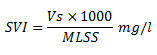
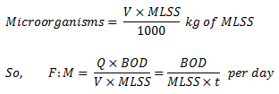
What is Activated Sludge? It is a FLOC (i.e body of micro-organisms gathered in a crowd) produced in a raw or settled sewage by the growth of bacteria and other organisms in the presence of dissolved oxygen and accumulated in sufficient concentrations by returning floc previously formed. Activated Sludge Process Activated Sludge Process is the biological method for treatment of wastewater. It was devised by Arden and Lockett in 1914. In this process a mixture of sewage and activated sludge is agitated and aerated in an Aeration Tank. Bacteria present in the activated sludge aerobically metabolize the organic matter present in the influent. The organic matter is oxidized to CO2, H2O, NH3 etc. and a portion of it is converted into new bacterial cells. The activated sludge is subsequently separated from the Mixed Liquor (mixture of sewage and activated sludge in the aeration tank) by sedimentation in the Final clarifier and wasted or returned to the aeration tank as needed. The treated effluent overflows the final clarifier. Sludge Settleability The degree of treatment in ASP depends upon the settleability of sludge in the final clarifier. The biological floc settles by gravity and leaves a clear supernatant for disposal. However, if filamentous micro-organisms grow in the aeration tank, they do not separate by gravity and contribute to BOD and Suspended Solids in the effluent. Excessive carry over of FLOC, resulting in the inefficient operation of final clarifier is referred to as Sludge Bulking. Conditions Promoting Growth of Filamentous Micro-Organisms Insufficient Aeration - Dissolved Oxygen (DO) Level Lack of Nutrients -Nitrogen (N), Phosphorous (P) Presence of toxic substances Low pH - Promotes fungal growth Over Loading i.e. High Food : Micro-Organisms (F:M) Ratio F : M Ratio F:M ratio is expressed in terms of kg of BOD applied per day per kg of MLSS. If Q is the sewage flow in cu meter per day and it has a BOD expressed in mg per liter then: If V is the volume of aeration tank in cu meter and it has MLSS concentration expressed in mg per liter then: Where t is the Aeration Time in days Sludge Volume Index (SVI) SVI Indicates sludge settling characteristics. It is the volume in ml occupied by one gram of settled suspended solids. An SVI from 50 to 150 indicates good settling characteristics. Advantages of ASP High BOD removals (greater than 95%) Low land areas required Odour free operation Treats industrial wastewater well Disadvantages of ASP Extremely sensitive and sophisticated Skilled operation is needed Sludge bulking problem High operating costs
-
Introduction Accurate and complete subsurface information is necessary for all types of civil engineering projects, for without this information it is not possible to arrive at a rational design for structure and proper construction procedures. Structures have failed because of inadequate or misleading subsurface data, and many so called successful structures could probably have been completed at much less cost because proper consideration have been given to obtaining more complete subsurface information. Boring and Sampling Methods Auguring is a simple method of putting down holes a few inches in diameter to depths up to 20ft in soft sediments. Trial pits and trenches in addition to providing samples of the deposits excavated, allow inspection of the rocks in the walls and floor over an area. Boreholes allow much greater depths to be penetrated. Boring methods are broadly of two kinds: 1. Percussion Drilling In percussion drilling the bit is suspended from the rods (or a cable) and is jumped up and down so that the rock is broken up by repeated rows. Water is added to the hole to keep the bit cool and make slurry and debris removed by means of a bailer. The pounded rock mixed with water from slurry, from which chips may be recovered for identification. The rate of progress of drilling, and the cost varies according to the hardness encountered. 2. Rotary Drilling Rotary drilling methods include mud rotary drilling and core drilling. In the former the bit is rotated, and is attached to hollow drilling rods through which a fluid mud is pumped continuously. The mud is returned to the surface through the annular space between the rods and the hole, bringing with it small fragments of rock which can be screened out and examined. The rods are usually in 20 ft lengths, and successively added to the assembly as the hole is lowered. 3. Core Drilling Core drilling uses a tabular bit with a lower cutting edge, which is rotated in the hole; many forms of bits are available, some containing diamonds and other hard abrasives for penetrating hard rocks. Diamond drills with a diameter of 2 to 4 inches are commonly used, for sampling, or in exploratory bore from underground workings and holes can be drilled at any angle. As the bit is rotated, a core is cut out and enters a barrel mounted above the bit. The length of the barrel controls the length of the core which can be obtained at any time. The core is recovered by drawing the drilling rod and barrel. The cost of core drilling is greater than for any other method and increase greatly with increasing depth of the hole; but the recovery of the core is a great advantage, as it yields information from great depth and is a sample of rocks drilled through. 4. Core Barrels The aim of structural drilling is to recover undisturbed core upon which measurements of structural features can be made. This can be achieved either by the multiple-tube core barrels or by the use of large diameter barrels. In the multiple-tube core barrel, the inner tube or tubes are mounted on a bearing so that they remain stationary, while the outer barrel, which carries the diamond bit, rotates. The core, cut out by bit, is transferred into the non-rotating inner barrel where it remains undisturbed until the barrel is removed from the hole. Removing the core from the barrel is the most critical part of the operation. The most satisfactory system is to use a split inner barrel which is removed from the assembly with the core inside it and then split to reveal undisturbed core. 5. Geophysical Methods Geophysical methods allow subsurface features to be located, mapped, and characterized by making measurements at the surface that respond to a physical, electrical or chemical property. These non-invasive measurements can be effectively used to provide reconnaissance to detailed geological information guide, subsurface sampling and excavation, and provide continuous monitoring. If all sites were simple (horizontally stratified geology with uniform properties), site characterization would be easy. Data from just one boring would be sufficient to characterize the site. However in most situations, this will not be the case. Even at sites where geology appears to be uniform, one must be alert to often-subtle variations that can cause significant changes in structural or hydrological properties. Traditional approaches to subsurface field investigations commonly rely only on the use of direct sampling methods such as boring of rock and soil samples, monitoring wells for gathering hydro geologic data points. Soil and rock sample programs and the placement of boring and wells are done mainly by educated guess work. Numerous pitfalls are associated with this approach that can result in an incomplete or even erroneous understanding of site conditions. These oversights are the cause of many structural and environmental failures. In many cases direct sampling alone is not sufficient to accurately characterize site conditions. This is the primary reason for the application of surface geophysical methods. Surface geophysical measurements can be made relatively quickly; they provide means to significantly increase data density. Because of the greater sample density, anomalous conditions are more likely to be detected, resulting in an accurate characterization of subsurface conditions. 5.1. Application There are four major areas where surface geophysical methods may be applied to environmental and engineering problems: 1) Assessment of natural geologic and hydro geologic conditions. 2) Detection and mapping of contaminant plumes, spills and leaks. 3) Detection and mapping of landfills, trenches or other underground structures and utilities. 4) Evaluation of soil and rock properties and man-made structures. The following is a summary of various geophysical methods: 6. Seismic Methods Seismic measurements involve the measurement of seismic waves travelling through the subsurface. Stratigraphy, structure, and material properties can be assessed with seismic methods. All applications of seismic methods are based on the fact that the elastic properties of soils and rocks determine the velocities of wave propagation through them. The higher the elastic modulus, for example, higher the velocity is. In rocks the dominant factors that influence the velocity are the crystallinity and porosity. Rocks having crystalline textures and low porosity have higher shock wave velocities just as they have high elastic moduli and compressive strengths. Shock waves in earth materials follow multiple paths from source to receiver. In the near surface, waves take a direct path from source to receiver and the measurements of elapsed travel time for measured distance results in the wave velocity through that material. Waves moving downward into the earth may be refracted and reflected at velocity interfaces. The ray-path diagram is a convenient method of showing wave propagation by direct, refracted and reflected paths. Unless otherwise noted, all velocities refer to compressional waves. Seismic data are obtained by recording shock-wave travel time between a source and a receiver, or geophone, for various chosen distances. Two general types of seismographs are used in engineering applications. One type permits the simultaneous, multichannel recording of shock-wave arrivals at a number of geophone locations from a single energy source such as a buried explosive charge or a weight-dropping system. The output from the geophones may be recorded in analog and digital forms in a variety of ways, all having a time base to permit extraction of elapsed travel times to each geophone location. Two advantages of multi-channel recording are; (1) single energy source for all geophone channels, and (2) more sophisticated filtering, recording, data processing, and printout capabilities than simpler single-channel seismographs. Disadvantages include higher firs cost, greater operating cost, large size, and often the need for greater peripheral support such as computer hardware and software. The second type of seismographs is a single-channel instrument that records shock-wave travel time from a source to a single geophone location. As a result, the operation must be repeated for different geophone distances until a suitable number of travel times have been obtained. Single-channel seismographs may record geophone output in several ways such as on an oscilloscope; on a chart, as in multichannel unit; or only as a first-arrival pulse time digitally (or by some other means). Timing systems are inherently a part of each system. Single e-channel seismographs are low initial cost, small size and provision for tailoring of geophone recording distances to the given site as work progresses. Disadvantages include time require for obtaining data, lack of single energy source for the entire geophone spread, and usually a restriction of use to refraction seismic surveys. 6.1. Seismic Refraction It is a method used to determine the P-wave velocity structure of the subsurface. Seismic P-waves are generated on the surface, propagate through the soil and rock, and are recorded by geo-phones at known distances from the source. When seismic waves encounter interfaces separating materials of different seismic velocities, the waves are refracted according to Snell's Law. At the critical angle for each interface (energy refracted 90 degrees) the seismic wave will travel along the interface with velocity of underlaying layer. A seismograph is used to record the travel times of these first arrivals, after which seismic velocities can be derived. Depths to the refracting layers can also be determined. Primary applications include determination of depth to bed rock and thickness of geologic strata, rippability and dredge-ability, and in-situ elastic modulus of soil and rock. It can provide data to depth of 100 ft or more and resolves up to 2 to 3 layers. It also provides a 2D cross-section of P-wave velocity. The source of seismic energy can be as simple as 8-pound sledge hammer. Deep measurements may require explosive as an energy source.If a velocity interface is not parallel with the surface, the velocities recorded at the surface are apparent rather than true velocities. The velocities recorded or plotted will be less than or greater than true velocity when energy is travelling down-dip or up-dip, respectively. The shallower down-dip end will exhibit a lower intercept time and critical distance compared to the deeper or up-dip end. 6.2. Seismic Reflection Seismic reflection measures the travel time of seismic waves from the surface downwards to geologic contacts where part of the seismic energy is reflected back to hydrophones at the surface. A reflection will occur from geologic strata when the reflection coefficient (derived from density and seismic velocity contrasts) between strata is sufficient. After raw data are processed, a cross-sectional picture of subsurface strata and anomalous conditions can be developed. Primary application is for determination of depth and thickness of geologic strata, structural and anomalous condition. The depth ranges from as shallow as 30 ft to greater than 100 ft. 6.3. Down-hole seismic surveys These are the simplest and cheapest method as they required only a single borehole. Seismic energy is generated on surface at a fixed distance from the top of the borehole. The travel times of the first-arrival seismic waves measured at regular intervals down the hole using string of hydrophones or in case of S-wave surveys, a single clamped tri-axial geophone that is gradually moved down the hole. P and S wave arrival time for each receiver location are combined to produce travel time versus depth curves for the complete hole. These are then used to produce total velocity profiles from which interval velocities and various elastic moduli can be calculated (in conjunction with density data from geophysical logging of borehole). 6.4. Cross-hole Seismic Surveys This involves measurement of the travel time of seismic energy transmitted between two or more boreholes in order to derive information on the elastic properties of intervening materials. One hole is used to deploy the source while the other hole(s) are used to detect the arrival of the seismic energy. The travel time of the seismic waves are derived from the first arrivals identified on the seismic trace for each short-receiver position and are used with the known distances between the short/receiver boreholes to calculate the apparent velocities (P & S) for each depth interval. This data is then used to derive a vertical profile of the various elastic moduli. The relationship between the velocity of seismic waves and the density and elastic properties of the materials through which they are travelling means that seismic techniques can be utilized to provide information on various geotechnical properties of the subsurface, such as Poisson's ration and shear modulus. The most common method of measuring these properties in engineering studies through the use of cross-hole seismic surveys. 6.5. Cross-hole Seismic Tomography Borehole seismic tomography involves the measurement of the travel times of seismic ray paths between two or more boreholes in order to derive an image of seismic velocity in the intervening ground. Data is collected using one hole for the seismic source (normally a speaker) and measuring one arrival time using strings of hydrophones in the other. Travel times are collected at regular intervals (usually 0.5 m to 2 m) all the way down the hole(s) for each short position. This results in a network of overlapping ray paths that can be used to model the velocity profile. The resulting velocity image is termed a tomogram and enables identification of anomalous velocity zones laying between the boreholes as well as imaging individual velocity layers. The primary applications of borehole seismic tomography is in engineering studies for the identification of features such as fault zones and voids when combined with S-wave survey, the data can additionally be used to provide information in material stiffness properties. 7. Electrical Resistivity Electrical resistivity measurements are made by placing four electrodes in contact with soil or rock. A current is caused to flow in the earth between on pair of electrodes while the voltage across the other pair of electrodes is measured. The depth measurement is related to the electrode spacing. The resistivity measurement represents the apparent resistivity averaged over a volume of the earth determined by the soil, rock, and pore fluid resistivity, along with the electrode geometry and spacing. In contrast to wave velocities in refraction seismology, resistivity values are not representative of specific physical properties of earth materials no do they remain constant over time. The flow of current through soil and rock is by ion conduction, which is dependent on a combination of the conductivity of the fluid present, porosity, and percentage of saturation. Dissolved salts in water provide for ion conductance of electrical current. The conductance that is the reciprocal of resistance is directly proportional to amount of dissolved salt in water, or salinity. The amount of fluid regardless of its salinity that can be present is controlled by the porosity of material. The more interconnected the pore spaces, the greater the ease of ion migration through the material. In addition, the degree of saturation that varies with season, in turn affects conductance (or in the context of this discussion resistivity). Seasonal fluctuations in resistivity of as much as 200% have been reported. The rock forming minerals normally are highly resistive to current flow. An exception, which complicates resistivity work, is the presence of clay minerals. The exchangeable ions in the clays may separate from the lattice and make the pore water conductive even though the formation water may not be saline. As a result, clays have low resistivity – whether occurring as clay-rich soils or as shales. If we are certain that the groundwater in an area is fresh, low resistivity is representative of clay. Conversely, freshwater (a poor conductor) will cause high resistivity when present in the poor spaces of a clean or clay-free soil or in the pores or joints of a porous or dense, relatively clay-free rock. Note, however, that there is nothing distinctive about the kind of material that has high or low resistivity values, as is the case with seismic velocities. For instance, it would be possible on the basis of high resistivity to drill expecting to encounter porous, freshwater-bearing sand and instead encounter tight sandstone. Also saline pore water in sand or porous or highly fractured rock gives low resistivity values that are also indicative of clay or shale. Because of these perplexing problems, there is the need for subsurface control of materials and thickness from either exposures or boreholes. 8. Magnetic There are two primary applications for magnetic measurements; 1) locating and mapping buried ferrous metals, and 2) mapping geologic structures. The presence of buried ferrous metals creates a local variation in the strength of the earth's magnetic field permitting the detection and mapping of buried ferrous metal. Total field measurements made with one magnetometer, and gradient measurements made with two magnetometers are commonly used. Magnetic gradient measurements are made by a gradiometer, which is simple two magnetic sensors separated by a constant offset. Magnetic measurements can be used for geologic mapping by responding to the magnetic susceptibility of soil and rock. Generally total field measurements are used for geologic mapping. The primary application is for mineral exploration and for characterizing geologic structures such as faults. 9. Microgravity A microgravity survey provides a measure of change in subsurface density. Natural variations in subsurface density include lateral changes in soil or rock density, buried channels, large fractures, faults, dissolution-enlarged joints and cavities. A microgravity survey consists of making sensitive gravity measurements at the micro Gal (µGal) level (1/1000 of a milliGal or 10E-9 of the earth's gravitational field) with a gravimeter. Gravity measurements are acquired at discrete points along a profile line or within a grid, and are corrected for instrument drift, tidal effects, elevation changes, and latitude. Gravity anomalies are directly related to lateral variations in subsurface density. This method is used to identify caves, voids, skin-holes and weathered zones. It is also used to map top of rock. It can also be used to identify man-made structures such as tunnels and mines. 10. Ground Penetrating Radar Ground penetrating radar (GPR) uses high frequency electro-magnetic waves to acquire subsurface information. Energy is radiated downward into the ground from a transmitter and is reflected back to receiving antenna. The reflected signals are recorded and produce a continuous cross-sectional profile of shallow subsurface conditions. Reflections of the radar wave occur where there is a change in the di-electric constant or electric conductivity between two materials. These changes are associated with natural hydro-geologic conditions such as bedding, cementation, moisture, clay content, voids and fractures. Large changes in dielectric properties often exist between geologic materials and man-made structures such as buried utilities or tanks. This technique is also used for the location of rebar in concrete nondestructive testing of man-made structures. Ground penetrating radar is also used to map void space behind concrete tunnel lining.
-
1. Introduction Subsidence is displacement of ground surface vertically over a broad region or at localized areas. It may be either a gradual lowering or a collapse. This can have costly effect on facilities and structures over a subsiding area. Subsidence results from a number of different mechanisms. It can occur as a consequence of natural processes. The dissolving of limestone, salt, or other soluble materials creates underground openings that may collapse. Collapse may also occur in the roofs of lava tubes in areas underlain by volcanic rock. Withdrawal of fluids from subsurface reservoirs can create human-induced subsidence. This type if subsidence has resulted from extracting oil, gas and ground-water. Underground mining is another mechanism for creating subsidence by creating subsurface openings. Natural solution of rock leading to collapse of the overlaying surface can be a rather spectacular form of subsidence. A single sinkhole 324-ft wide and 100-ft deep was formed by collapse on May 8-9, 1981, in Winter Park, Florida. It destroyed a house, several cars, streets, parts of neighboring buildings, and the city swimming pool, causing losses estimated to exceed $2 million. Groundwater withdrawal for surface uses or dewatering of quarries and mines causes a general lowering of the water table. Construction activities are a less-common cause of collapse. Subsidence because of construction can result from loading the ground surface over a cavity or from the diversion of surface water, thus changing the groundwater system and increasing sinkhole development. Subsidence caused by underground mining results in severe economic losses in some areas. It is estimated that damage amounting to $30 million annually results from subsidence over abandoned coal mines. Underground mining notably coal mining, creates subsurface openings. Rock layers bridging these voids may fracture and collapse into the opening, with resultant lowering of the ground surface. Subsidence causes differential settlement, with the greatest amount near the center of the opening. Associated with this differential settlement are ground cracks. The extent and size of cracks will change until subsidence is complete in an area. Withdrawal of oil, gas and water has produced subsidence that has resulted in extensive losses in Arizona, California, and along the gulf coast of Texas. Subsidence causes damage in several ways. The most obvious causes are in tilting, cracking, and shearing of structures where subsidence produces differential settlement. Large-scale collapse can completely destroyed some structures. Destruction results when water-containment structures such as reservoirs and canals are breached. Subsidence causes damage impairing the function of some surface facilities. It can create low points in pipelines and alter the alignment of microwave transmission stations. A more-subtle consequence of subsidence is ground lowering that makes more land subject to flooding. 2. Evaluating Subsidence Processes It should be clear from our discussion that evaluation of subsidence processes depends on a variety of methods. Evaluating possible underground openings will require a very different approach than estimating subsidence from fluid withdrawal. The potential of solution-caused subsidence depends on the presence of limestone or other soluble rock type. Examining the natural subsidence occurring where these rocks are present serves as an initial indicator. For example, a sinkhole-density map compiled by means of aerial photography is useful measure of relative collapse potential. Similarly, the potential for subsidence from underground mining exists only where mining is active or was conducted in the past. Historical records or the details surface surveys normally conducted by many present day mines provide a basis for evaluating subsidence potential. The extent of subsidence depends on factors such as: 1) thickness of mined coal, 2) mine geometry and mining methods and 3) thickness, lithology, structure, and hydrology of bedrock and surficial material in the mining area. Detecting solution cavities or abandoned mine openings is mostly reliably done with the drilling. However, expense limits such drilling over large areas. Earth-resistivity surveys can detect openings at depths up to 25m. Gravity surveys are marginally successful; only large openings near the surface are detectable. Subsurface radar techniques proved too unreliable for practical use. There are two field-based techniques for subsidence prediction where fluid is being withdrawn. One is the depth porosity method, and other is aquitard-drainage method. Estimating subsidence in an area where fluid withdrawal is being initiated is best done with the depth-porosity method. For the more complicated situation in which subsidence is already active, the aquitard-drainage method is recommended. Ground failures in areas subsiding owing to fluid withdrawal can be predicted. These ground failure range from tension cracks to surface faults. Prediction of ground failure in areas where deformation is underway requires monitoring of surface conditions for sign of failure. In areas not yet subject to subsidence, prediction requires determining the particular surface conditions conducive to failure. 3. Mitigating the Effects of Subsidence Processes Controlling land use to avoid large-scale changes in the regional water table is one way to avoid subsidence in areas underlain by soluble rock. Avoiding withdrawal overdraft from compressible groundwater aquifers is equally effective in avoiding subsidence. Reservoirs from which oil, gas, or geothermal fluids is being withdrawn can be re-injected with water to compensate for the lost fluids. In some instances, subsidence over mines need not result in structural damage. This requires knowing the specific factors that influence subsidence at that locality and conducting mining in a manner that permits a general lowering of the entire area in which a structure is situated. This minimizes the differential settlement responsible for most of the distress to structures. Structures damaged or impaired by subsidence can be restored in many cases, this involves sealing the cleaned-out sinkhole, restoring the ground surface, ensuring that surface water to site is minimized, and promoting groundwater flow down gradient from the repair location. Some problems with solution-related subsidence are human related. This is especially true where natural sinkhole is used to drainage. Diverted water can increase the groundwater gradient in areas, leading to greater subsidence. Subsidence controls over mined areas generally takes the form of either providing selective support for the structure or filling the underground space to halt further subsidence. In an effort to control subsidence affecting an electric substation in Pennsylvania, both approaches to dealing with subsidence were used. Selective support involved placing drilled piers and piling seated into rock below the base of the mined coal seam. Fly ash was injected through drill-holes to fill some underground openings. In 15 selected locations, grout columns were constructed.